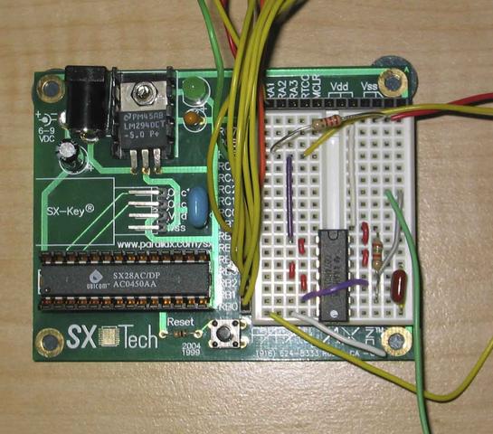
Here’s a picture of the prototype coming together.
From the top down on the breadboard, you see a pull-up resistor, on the input that comes in on the yellow wire. The output comes out of the grey wire on the right hand side(and is going to a scope on the green wire heading off the bottom of the board.
The RC network that makes up this one-shot negative going oscillator is on the right hand side. This controls the width of the output pulse, which in this is case is 1.5us.


Add comment