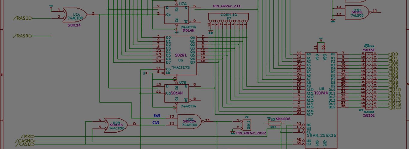
While I shouldn’t be surprised, my SX hardware issue is related to double one’s, where the SX sees transitions back to back, and writes back to back 1’s into memory.
This is assuming there aren’t memory-related issues.
I’m not surprised because I enforce the number of consecutive zeros by forcing the SX to go into an idle mode if it sees more than three consecutive zeros. Since the standard “idle” condition on the drive, when its not spitting out data is a high, or a “0”, then I don’t want my SX trying to process these.
I don’t enforce a double-one’s rule, but I could easily just check to see if we’ve seen an edge, and no other zero, and then simply not write the one. I don’t know if this is the answer though. It would be better to know WHY we’re detecting two transitions back to back.
Most of the actual action on the SX happens within the ISR. While I haven’t looked at it in awhile, my code is really nice and simple. I like it.
I’ve upped the assembly source here. It’s short and easy to understand.
A quick run-down on how it works :
Once interrupts are enabled by commanding my SX main code to turn on the motor etc, the interrupt fires regularly every 2us. If the SX hasn’t seen any edges, it simply exists, because it has to first see the initial transition before doing anything. Transitions that occur on the read data lead of the floppy trigger the falling edge detection on a certain lead, and my SX has been setup to enter the ISR upon that trigger firing.
Upon entering the ISR, the ISR has to figure out WHY it was called. Was it called because the regular 2us timer expired, or was it called because a transition occurred? It makes this determination by looking at the value of RTCC (real time clock counter?)
Since the rollover of RTCC(which is constantly increasing in the background independent from any user(my) code) from 255->0 is what triggers the ISR firing in my regular call to the ISR, the values of RTCC are likely to be very low if activated this way. It takes a certain number of instructions to actually activate the ISR, and I have a line of code or two before checking RTCC, so normal firing should have an RTCC value of 4 or 5.
If, on the other hand, the ISR was activated as a result of the falling edge trigger, then the RTCC value is likely to be much higher, usually in the 220’s or so.
If you see this on a scope, it looks really good, with the transition being quickly detected and the rollovers happening neatly within the center of each 2us bitcell.
I also sync to the edge, so that as transitions are detected, it resets that clock, and so the next rollover will happen in the middle of the next bitcell.
The only other thing that I do in the ISR is write the 0 or 1 to the fram, which takes a measly 5 instructions. I also keep track of the number of stored bits, so that the main code knows when a full 13824 bytes has been stored. Remember, I’m storing a bit at a time, and so thats 110,000 bits, and it requires using 3 bytes of storage (lobyte, hibyte, and superbyte) for the count.
Note that the SX doesn’t queue or store interrupts. It has a feature called “Auto Interrupt Disable”. Interrupts that “arrive” while the SX is already processing another interrupt are ignored.
It takes much longer to describe what’s happening in the code than if you just read it.


Add comment