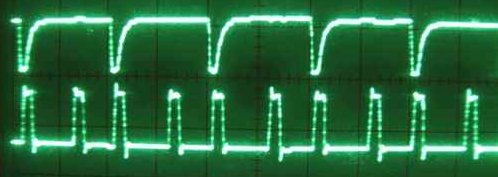
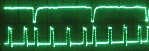
These are all 2us per division on the scope. Top trace is the actual MFM, bottom trace is the entering and exiting of my ISR. You should see an entry into the ISR for every falling edge, and every ~2us afterwards.
1k, 680, and 490 in order.


These are all 2us per division on the scope. Top trace is the actual MFM, bottom trace is the entering and exiting of my ISR. You should see an entry into the ISR for every falling edge, and every ~2us afterwards.
1k, 680, and 490 in order.


I swear I already posted about this but heck if I can find the post. Anyways, here’s a photo of a bug katcher installed on Agnus on a Commodore Amiga 500. This gives me the ability to attach a logic analyzer to...
Dave just posted this! I’m so glad to see him take this on!
So looking at a lot of raw data is pretty tough, but matlab handles it with ease. So the above image shows a sample amiga track from a brand new disk, just recently formatted, within the amiga. It is basically as...

techtravels.org is a blog that features home-grown open-source hardware and software projects.
Copyright © 2018 techtravels.org Powered by WordPress
One picture is worth one thousand words, and I can see three of them 🙂
The images are perfect. There’s only one thing I can’t help but notice: let’s look at the last picture, bottom trace. First we see the edge detection (say, let it occur in T=4.05us). Next, there is a timeout, and the debug spike occurs in T=6.1us. Second and third timeouts take place at T=8.15us and T=10.2us, respectively.
In other words, the ISR ‘ticks’ are slightly delayed from where they would seem to be on the scale, obviously due to the fact that the ISR takes some time. And this error adds up. Can you decrease your timeout constants again just a little to get rid of this skew?
I will definitely try that out.
I currently have my timeouts set at 2.02us. Now the SX automatically adjusts the timeouts by the actual length of the ISR, ie it provides “jitter-free” interrupts, so the timeouts should always happen in multiples of 2.02 after the edge is detected. Now there are actually a couple of instructions that run before the clock gets reset(immediately following an edge), which is why we should see the first timeout happen a little later than expected. The next two timeouts(in the case of a ‘1000’) should be last entry + 2.02us.
But here’s the catch, the clock gets reset every time an edge happens. So this drifting, or “slipping” shouldn’t occur past the 3rd timeout.
So really, the error shouldn’t add up, should it?
BTW: Do you like and understand my new simplified isr? (https://techtravels.org/?p=120)
Ah, I see. You are right, the drift is necessary. Still it is etching to tweak the timeout, now to increase it slightly 🙂
Yes, the rewritten ISR is much easier for me to read.
I recall you wrote on the subject of stacking interrupts. What happens if an edge occurs while we’re inside the ISR? will some interrupt flag be set so that when the ISR is finished, it will fire again?
You’ve probably seen this topic:
https://www.parallax.com/sx/support_faqs.asp#Question%20#6
Quote:
‘For example, assume two interrupt sources: RTCC and RB0 and the ISR is currently servicing the RTCC roll-over. If you disable interrupts by setting the RTI bit at the top of the interrupt service routine, the next interrupt on RB0 will be queued. You must enable interrupts by clearing the RTI bit just before the end of your interrupt service routine. Should the RB0 interrupt arrive before interrupts are disabled at the top of the interrupt service routine, that interrupt will be ignored. In this particular application, it may be better to simply check the pending register before returning from the interrupt service routine section that handles the RTCC roll-over interrupt.’
As a matter of fact, I actually quoted that same answer in a previous post 🙂
Ok, from the SX Development manual:
“Auto Interrupt Disable: As soon as an interrupt occurs, additional interrupts are automatically ignored by the SX chip until the interrupt routine is completed. This prevents the interrupt routine from being interrupted and prevents the loss of return vector data…………..”
“Note: Should additional interrupts occur, the SX chip does not automatically queue up interrupts for future processing…….”
“Interrupt queuing: If an external interrupt occurs during the interrupt routine, the pending register will be updated but the trigger will be ignored unless interrupts had first been turned off at the beginning of the routine and turned on again at the end. This also requires that the new interrupt doesn’t occur before interrupts are turned off in the interrupt routine. If there is a possibility of extra interrupts occurring before they can be disabled, the SX will miss those interrupt triggers.”
And I’ve read those FAQ’s about a million times, btw 🙂
With all this being said, if an edge occurred while we were in an RTCC rollover, the pending register would still be updated(but isr would not fire again), and the next time I enter an RTCC rollover, it would appear to the ISR that we had shown up due to EDGE, when in fact it was a rollover condition.
This was one reason why my last version of the ISR checked the value of RTCC upon entering the ISR instead of using the pending register.
Hrrmmmm… Here’s the only problem. My timing appears to be good enough that we should never be in the ISR when an edge goes off. I have never caught this on the scope, and its one of those things I look for religiously.
I think I’m going to check the pending register before leaving the ISR and set a breakpoint if that happens……. lets see if we’re missing an edge.
Just ran the test.
Negative: I’m not seeing any EDGE’s occurring while I’m inside the interrupt. I check it right before I leave, and the pending register bits are not set.
I also tried turning interrupts OFF when I enter and ON when I leave, and that has no noticable effect either.
Just to put sort of the pullups thing to bed:
The Samsung manual I referred to in an earlier post says to use a Schmitt-Trigger, which I am, and to use 150 ohm – 2.2kohms. It says 1k ohm is recommended. I’m leaving mine at 680 for the time being.
[…] Data stored on the disk is done by sending pulses to the floppy drive. The pulses are “active low”. The floppy drive stores a pulse on the disk every 4, 6 or 8 microseconds apart (for a standard density disk) which represent the binary values 10, 100 and 1000 respectively. You can see these transitions here: https://techtravels.org/?p=123 […]