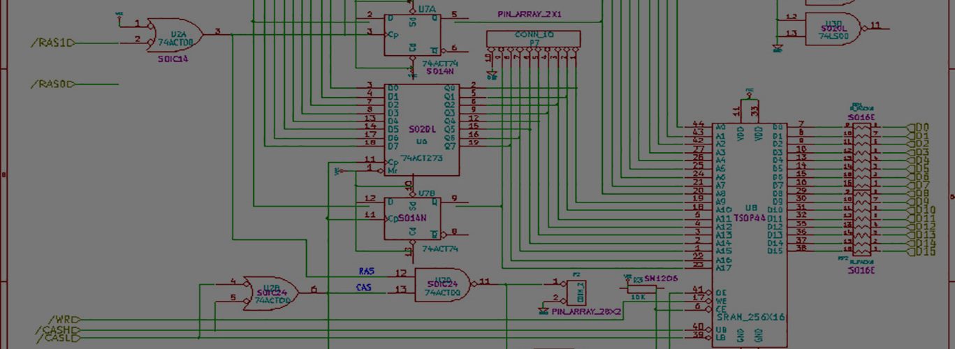
So you’ve seen me talk about good data and bad data. But what’s the difference?
Good data looks like the picture I posted awhile back here.
Note the very even spread of 4—4—8. Every pattern is recognizable.
Bad data, though I don’t have a picture, has many edges that are closer together, separated by long runs of empty space. These lows, instead of being roughly 4us, 6us, or 8us long, they are weird — a common one is around 2us +/-. Some of them even smaller like 1.5us.
This data is actually coming off the floppy — or at least from the drive. Eject the floppy disk, and no data comes out. This is a nice refreshing change from the amiga floppy that always seemed to be spitting out data.


Have you tried to replace either drive, or floppy, or your power supply?
Not yet. Do you think I fried something? Drive is easy enough. I might have another one lying around. I have another test floppy I created, although the one I have has always been write-protected. Power supply is a little harder, I’m using one that came with a USB-IDE converter. I’ve used this supply recently to hook up a hard drive, and it worked as expected.
I’ve been trying to completely eliminate my SX from the test of the drive, just by shorting pins 10 and 14 to ground, which is Motor Enable (drive A) and Drive Select A. Motor first, then select.
The idea is that if I can’t get the drive working by itself, then I sure as heck can’t have my SX control it.
The drive was spitting out data that looked good on the scope not all too long ago.
I’d also suspect some floppy bus signal which, if not applied or applied poorly, could affect the READ DATA flow.
Just for the record – you do have all the rest floppy bus signals correctly terminated or set up don’t you? like the WR direction line, or whatever it is.
A screenshot of that bad data from your scope would be handy.
As usual Tim, you’ve hit right on the nose.
There were some unconnected leads that caused the problems.
I took pins 22, 24, and 28 (Write Data, Write Enable, and Write Protect) and tied them high, and the data now looks correct.
I was trying to keep as minimal of an interface as possible, but I guess leaving those leads floating is a bad idea.
Can I get your thoughts on the fact that I connect my port pins on my SX controller directly to the interface on the drive? Is this safe thing to do?
Would a resistor help prevent too much current flow and frying a pin(on either side)? If so, what values should I be using?
I’m guessing ohms law applies, but while I know ohms = volts/amps, I’m not sure that 1250 ohms = 5v/.004 tells me much. I measured the 4ma on one lead awhile back when I fried that pin.
Thanks as usual
I am glad you now have one problem less.
In general, it is better to have all signals of the floppy bus tied to +5v via, say, 10K resistors. This is pretty much safe for the bus, and will give you decent protection against noise on non-used lines.
As soon as your SX runs at 5 volts also I guess you can connect it to floppy directly. I used to add 560 ohm resistors between my AVR pins and floppy signals, I can’t recall the reason I did this – probably because I ran out of free pins on my AVR and had to use these lines in a tricky way to also poll buttons.
To the best of my knowledge, all floppy output signals are open collector. That is, in order to accept these right you have to tie them to +5v via spoken resistors. In my experiments values like 1k-10k worked all right, although I had to use 1k resistors for READ DATA line since my wiring was pretty lengthy if I may say so and its stray capacitance used to distort signal shape significantly.
The bottom line is that you needn’t use any additional resistors in series with floppy output signals. These (if I get it right) source current to your SX which I believe won’t take more than it needs.
On the other hand, your SX output signals must have limited current sourcing capabilities. I doubt the floppy inputs will sink every milliampere you give it, but it indeed is better to be on the safe side.
Take a look in SX datasheet. (For some given AVR, I can get as much as 10mA per output, but not more than 40mA for the whole chip. Your limitations can be similar) Considering we’re speaking to a CMOS or TTL logic inside the floppy, let’s assume 1mA as a good working current value. Then, dividing 5 volts by 0.001A gives us 5K.
In the end, you can always throw these resistors away should they work for you not 🙂
I have enough problems I’m happy too! 🙂
I used 1K as a pull-up resistor on my READ DATA line as well. I did because it made the signal look the best on the scope. I know that’s a little subjective, but it made the rise time reasonably short —- I noticed different values seemed to alter this time.
My SX datasheet says sink/source is 30mA.
Thanks
reminder to self: power off the drive and back on if you start getting bad data again. The drive can go into a wierd mode if you don’t select deselect etc properly. related to the write leads as well.
When in doubt, power it off and back on.